
Industrial 3D Printing & Design Services in Stuttgart
From a single prototype to small-batch production – with a mechanical engineering background and process-controlled FFF printing.
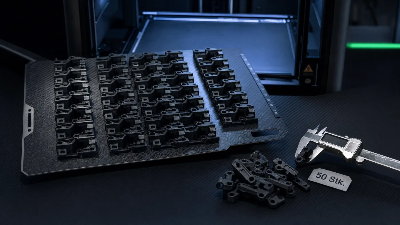
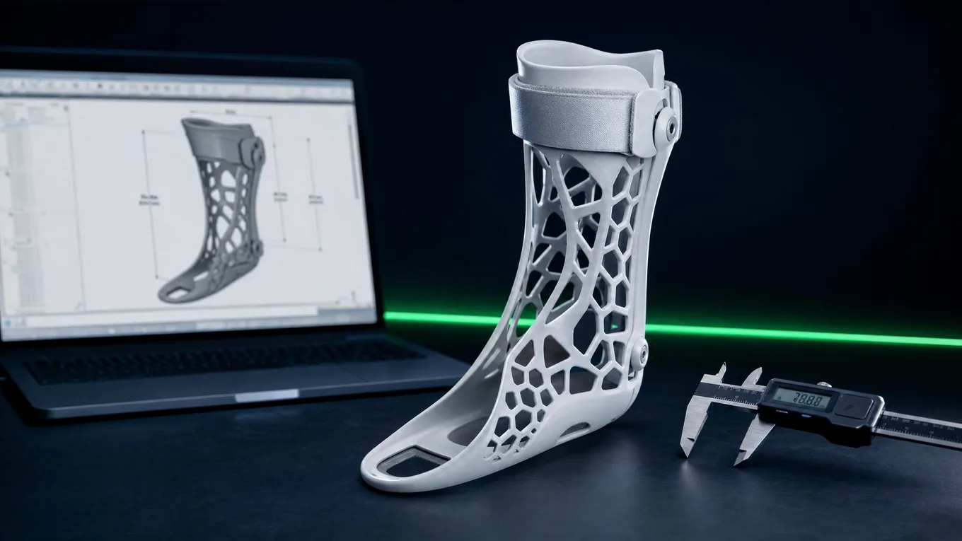
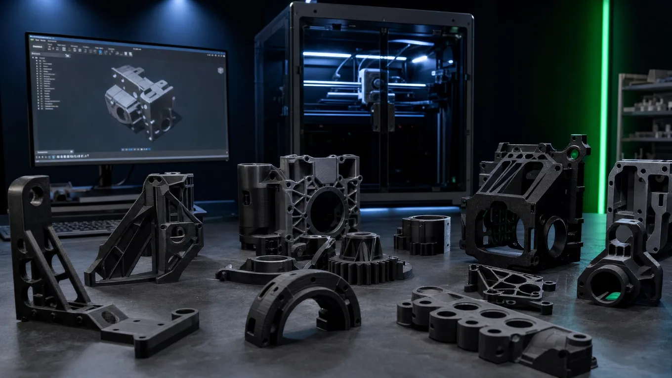
FFF 3D Printing
Fused Filament Fabrication (FFF) on calibrated industrial hardware. Every print job runs with material-specific parameters – print temperature, layer thickness, infill strategy and layer orientation are configured per part.
The result: reproducible parts with defined mechanical properties instead of random results from overheated home printers.
- Layer thickness 0.10 – 0.30 mm
- Part size up to 400 × 400 × 500 mm (single part)
- Dimensional accuracy typically ±0.2 mm
- Infill 15% – 100% depending on load case
- Support optimization for minimal post-processing effort
Technical Parameters
| Materials | 37 materials – overview → |
| Layer thickness | 0.10 – 0.30 mm |
| Max. part size | 400 × 400 × 500 mm |
| Dimensional tolerance | ±0.2 mm typical |
| Surface finish Ra | 10 – 25 µm (as-printed) |
| Surface finish Rz | 50 – 125 µm (as-printed) |
| Minimum lead time | 2–3 business days |
Design Consulting
As a state-certified mechanical engineering technician (Bachelor Professional), technical part analysis isn't an add-on service – it's the standard. Every inquiry is evaluated from an engineering standpoint:
- Wall-thickness analysis for printability
- Recommended optimal layer orientation for the load case
- Tolerance-chain assessment for fits
- Identification of undercuts and alternative geometries
- Material recommendation based on requirement profile
Design consulting is included in the inquiry – no separate fee.

Part Optimization
Parts from classic machining or injection molding can't be manufactured 1:1 in 3D printing if you want the same result. Additive manufacturing has different strengths – and different weak points.
On request, CAD data is analyzed for additive-manufacturing-oriented design and optimization suggestions are worked out:
- Reducing support structures through geometry changes
- Topology optimization for weight reduction
- Wall-thickness adjustment for defined deformation behavior
- Interface optimization for assembly and joining connections

Common Optimizations
- Eliminate undercuts Printing without support possible
- Ribs instead of solid material Up to 60% material reduction at the same stiffness
- Optimize layer orientation Maximize tensile strength in the main load direction
- Adjust fits Account for 3D-print tolerances from CAD
Process Control
Reproducible parts don't happen by chance. Every order is manufactured on validated print profiles – calibrated per material, not from a default preset off the internet.
Filament drying, print orientation aligned to the main load direction and dimensional checks with a caliper before shipping are standard parts of every order.
- Vacuum storage and drying of moisture-sensitive materials
- Material-specific print profiles (temperature, flow rate, cooling)
- Print orientation aligned to the part's main load direction
- Dimensional check with a digital caliper (0.01 mm resolution)
- Visual inspection for layer defects, stringing and surface quality

Prototyping & Small-Batch Production
Prototyping
Single parts and small quantities for development, sample testing and functional tests. Ideal when geometry or material isn't finalized yet.
- 1 unit up to approx. 10 units
- Express lead time on request
- Iteration loops possible
- Design feedback included
Small-Batch Production
For repeatably accurate parts in quantities up to 500 units per order, larger quantities on request. Process parameters are documented to ensure consistent quality across multiple production lots.
- 5 to 500 units per lot, larger quantities on request
- Parameter documentation for follow-up orders
- Unit price drops with quantity – setup only happens once
- Framework agreements on request
Frequently Asked Questions About Our Services
How does FFF 3D printing differ from classic CNC machining for single parts?
FFF 3D printing needs no tooling and no fixture – every part is economical from unit 1. CNC machining involves high setup effort for single parts and only pays off at larger series. FFF also enables internal channels, undercuts and topology optimizations that can't be machined. Dimensional tolerance in FFF is typically ±0.2 mm; CNC reaches ±0.01–0.05 mm. For precision fits, FFF parts are mechanically post-processed or fitted with heat-set threaded inserts.
What post-processing options does 3D Fabrikant offer after printing?
Standard post-processing includes: support removal, thread cutting (M2–M12), installation of heat-set threaded inserts (Heli-Coil, Böllhoff Ensat), sanding and grinding of visible surfaces, and basic painting. Complex surface finishing (RAL-color painting, chemical smoothing for ASA) is available on request. Every post-processing step is itemized separately in the quote.
What is DfAM – Design for Additive Manufacturing – and why is it relevant?
DfAM (Design for Additive Manufacturing) means adapting a CAD geometry to the specific capabilities and constraints of the FFF process. Relevant factors: wall thickness ≥ 1.2 mm, overhang angles ≤ 45° for support-free printing, orienting bores horizontally, accounting for fiber orientation in CF materials, and correcting fit dimensions for print shrinkage. 3D Fabrikant performs a DfAM analysis for every inquiry – at no extra charge.
Does 3D Fabrikant offer small-batch production with consistent quality across multiple lots?
Yes. For small-batch projects, all print parameters are documented (temperature, layer thickness, infill, flow rate, orientation, material batch number). Follow-up orders use the same parameter set – parts are reproducible. Material batches are noted; if a different batch is used, a test print is run before series production. Framework agreements with agreed unit prices are possible.
What are the minimum requirements for submitted CAD data?
CAD data should be submitted as STEP (.step/.stp) or STL. STEP is preferred for parts with fits or threaded bores (dimensionally accurate geometry). STL is sufficient for visual prototypes. Requirements: closed solid bodies (watertight geometry), no self-intersecting surfaces, minimum STL resolution ≥ 0.01 mm triangle size. If there are issues with file quality, you'll receive feedback.
More questions → Full FAQ page
Ready for Your Inquiry?
Send us your part description or CAD data. You'll get a response within 24 hours.
Request a Project →